
An ATX motherboard
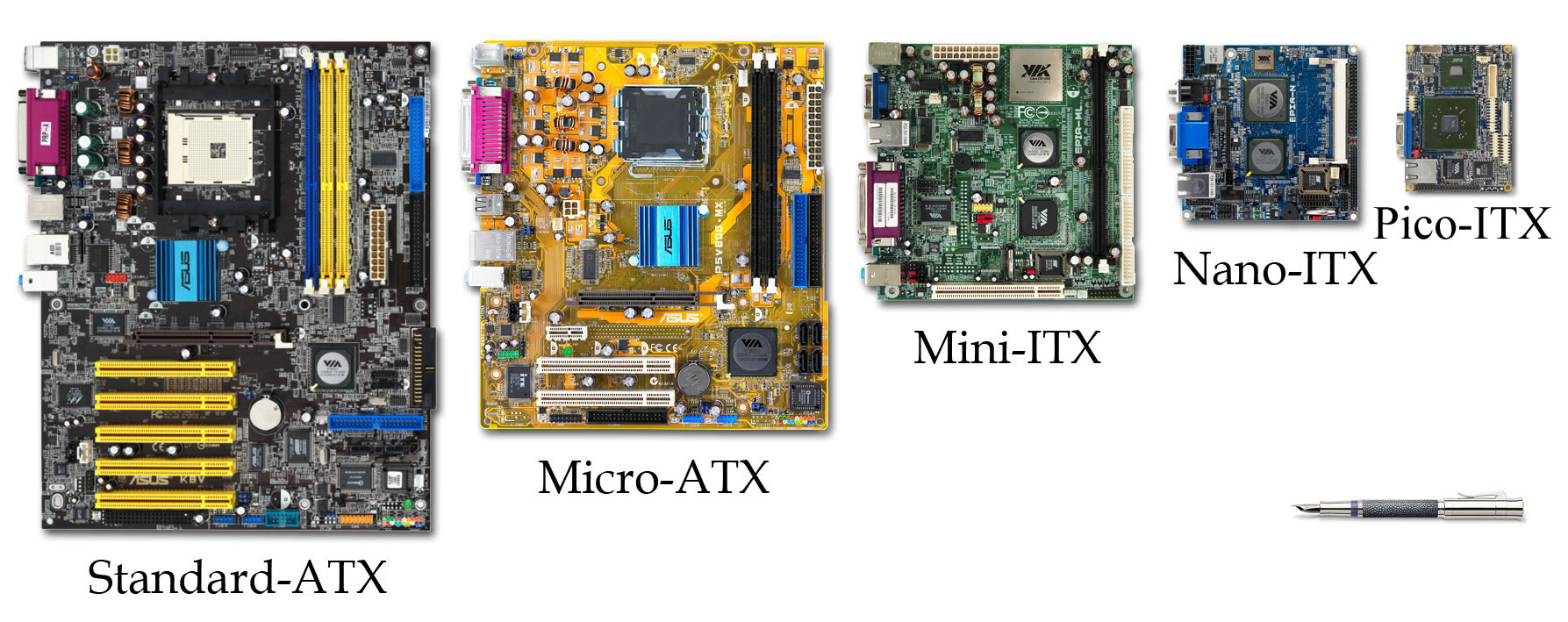
Comparison of some common motherboard form factors
ATX (Advanced Technology eXtended) is a motherboard and power supply configuration specification developed by Intel in 1995 to improve on previous de facto standards like the AT design. It was the first major change in desktop computer enclosure, motherboard and power supply design in many years, improving standardization and interchangeability of parts. The specification defines the dimensions; the mounting points; the I/O panel; and the power and connector interfaces among a computer case, a motherboard, and a power supply.
ATX is the most common motherboard design. Other standards for smaller boards (including microATX, FlexATX, nano-ITX, and mini-ITX) usually keep the basic rear layout but reduce the size of the board and the number of expansion slots. Dimensions of a full-size ATX board are 12 × 9.6 in (305 × 244 mm), which allows many ATX chassis to accept microATX boards. The ATX specifications were released by Intel in 1995 and have been revised numerous times since. The most recent ATX motherboard specification is version 2.2. The most recent ATX12V power supply unit specification is 2.4, released in April 2013. EATX (Extended ATX) is a bigger version of the ATX motherboard with 12 x 13 inch dimensions. An advantage of having an EATX motherboard is dual socket support.
In 2004, Intel announced the BTX (Balanced Technology eXtended) standard, intended as a replacement for ATX. Some manufacturers introduced the new standard; however, in 2006 Intel discontinued any future development of BTX. As of 2020[update], the ATX design still remains the de facto standard for personal computers.
Connectors[]

.jpg)
ATX I/O plates for motherboard rear connectors
On the back of the computer case, some major changes were made to the AT standard. Originally AT style cases had only a keyboard connector and expansion slots for add-on card backplates. Any other onboard interfaces (such as serial and parallel ports) had to be connected via flying leads to connectors which were mounted either on spaces provided by the case or brackets placed in unused expansion slot positions.
ATX allowed each motherboard manufacturer to put these ports in a rectangular area on the back of the system with an arrangement they could define themselves, though a number of general patterns depending on what ports the motherboard offers have been followed by most manufacturers. Cases are usually fitted with a snap-out panel, also known as an I/O plate or I/O shield, in one of the common arrangements. If necessary, I/O plates can be replaced to suit a motherboard that is being fitted; the I/O plates are usually included with motherboards not designed for a particular computer. The computer will operate correctly without a plate fitted, although there will be open gaps in the case which may compromise the EMI/RFI screening and allow ingress of dirt and random foreign bodies. Panels were made that allowed fitting an AT motherboard in an ATX case. Some ATX motherboards come with an integrated I/O plate.
ATX also made the PS/2-style mini-DIN keyboard and mouse connectors ubiquitous. AT systems used a 5-pin DIN connector for the keyboard and were generally used with serial port mice (although PS/2 mouse ports were also found on some systems). Many modern motherboards are phasing out the PS/2-style keyboard and mouse connectors in favor of the more modern Universal Serial Bus. Other legacy connectors that are slowly being phased out of modern ATX motherboards include 25-pin parallel ports and 9-pin RS-232 serial ports. In their place are onboard peripheral ports such as Ethernet, FireWire, eSATA, audio ports (both analog and S/PDIF), video (analog D-sub, DVI, HDMI, or DisplayPort), extra USB ports, and Wi-Fi.
A notable issue with the ATX specification was that it was last revised when power supplies were normally placed at the top, rather than the bottom, of computer cases. This has led to some problematic standard locations for ports, in particular the 4/8 pin CPU power, which is normally located along the top edge of the board to make it convenient for top mounted power supplies. This makes it very difficult for cables from bottom mounted power supplies to reach, and commonly requires a special cutout in the back plane for the cable to come in from behind and bend around the board, making insertion and wire management very difficult. Many power supply cables barely reach or fail to reach, or are too stiff to make the bend, and extensions are commonly required due to this placement.
Variants[]
- Main articles: Computer form factor


ATX, Mini-ITX, and AT motherboard compatible dimensions and bore positions


ATX motherboard size comparison; rear is on left. FlexATX (229 × 191 mm) microATX (244 × 244 mm) Mini ATX (284 × 208 mm) Standard ATX (305 × 244 mm) Extended ATX (EATX) (305 × 330 mm) WTX (356 × 425 mm)
Several ATX-derived designs have been specified that use the same power supply, mountings and basic back panel arrangement, but set different standards for the size of the board and number of expansion slots. Standard ATX provides seven slots at 0.8 in (20 mm) spacing; the popular microATX size removes 2.4 inches (61 mm) and three slots, leaving four. Here width refers to the distance along the external connector edge, while depth is from front to rear. Note each larger size inherits all previous (smaller) colors area.
Note: AOpen has conflated the term Mini ATX with a more recent 15 × 15 cm (5.9 × 5.9 in) design. Since references to Mini ATX have been removed from ATX specifications since the adoption of microATX, the AOpen definition is the more contemporary term and the one listed above is apparently only of historical significance. This sounds contradictory to the now common Mini-ITX standard ( 17 × 17 cm (6.7 × 6.7 in) ), which is why referring to such a product as Mini ATX is only going to confuse people. A number of manufacturers have added one, two or three additional expansion slots (at the standard 0.8 inch spacing) to the standard 12-inch ATX motherboard width.
Form factors considered obsolete in 1999 included Baby-AT, full size AT, and the semi-proprietary LPX for low-profile cases. Proprietary motherboard designs such as those by Compaq, Packard-Bell, Hewlett Packard and others existed, and were not interchangeable with multi-manufacturer boards and cases. Portable and notebook computers and some 19-inch rackmount servers have custom motherboards unique to their particular products.
| Form factor | Originated | Date | Max. size[lower-alpha 1] width × depth |
Slots | Notes (typical usage, Market adoption, etc.) |
|---|---|---|---|---|---|
| ATX | Intel | 1995 | 12 × 9.6 in (305 × 244 mm) | 7 | Original, successor to AT motherboard |
| SSI CEB | SSI | ? | 12 × 10.5 in (305 × 267 mm) | ? | Compact Electronics Bay |
| SSI MEB | SSI | 2011 | 16.2 × 13 in (411 × 330 mm) | 12 | Midrange Electronics Bay |
| SSI EEB | SSI | ? | 12 × 13 in (305 × 330 mm) | ? | Enterprise Electronics Bay |
| SSI TEB | SSI | ? | 12 × 10.5 in (305 × 267 mm) | ? | Thin Electronics Bay, for rack-mount, has board component height specification |
| microATX | Intel | 1997 | 9.6 × 9.6 in (244 × 244 mm) | 4 | Fits in ATX, and EATX cases. |
| FlexATX | Intel | 1997 | 9 × 7.5 in (229 × 191 mm) | 3 | |
| Extended ATX (standard) | Supermicro / Asus | ? | 12 × 13 in (305 × 330 mm) | 7 | Screw holes not completely compatible with some ATX cases. Designed for dual CPUs, and quad double slot video cards. |
| Extended ATX (commonly) | Unknown | ? | 12 × 10.1 in (305 × 257 mm) 12 × 10.4 in (305 × 264 mm) 12 × 10.5 in (305 × 267 mm) 12 × 10.7 in (305 × 272 mm) |
7 | Screw holes not completely compatible with EEB |
| EE-ATX | Supermicro | ? | 13.68 × 13 in (347 × 330 mm) | ? | Enhanced Extended ATX |
| Ultra ATX | Foxconn | 2008 | 14.4 × 9.6 in (366 × 244 mm) | 10 | Intended for multiple double-slot video cards, and dual CPUs, |
| XL-ATX | EVGA | 2009 | 13.5 × 10.3 in (343 × 262 mm) | ? | |
| XL-ATX | Gigabyte | 2010 | 13.58 x 10.31 in (345 x 262 mm) | 7 | |
| XL-ATX | MSI | 2010 | 13.6 × 10.4 in (345 × 264 mm) | 7 | |
| WTX | Intel | 1998 | 14 × 16.75 in (356 × 425 mm). | 9 | Discontinued 2008 |
| Mini-ITX | VIA | 2001 | 6.7 x 6.7in (170 × 170 mm). | 1 | Originally designed for home theatre or other fanless applications |
| Mini-DTX | AMD | 2007 | 8 × 6.7 in (203 × 170 mm) | 2 | HP supported with Pavilion Slimline series using AMD CPUs. |
| BTX | Intel | 2004 | 12.8 × 10.5 in (325 × 267 mm) | 2 | Canceled 2006. Also micro, nano, and pico variants. Not generally compatible with ATX mounting. |
| HPTX | EVGA | 2010 | 13.6 × 15 in (345 × 381 mm) | 9 | Dual processors, 12 RAM slots |
| SWTX | Supermicro | 2006 | 16.48 × 13 in (419 × 330 mm) and others |
4 | Quad processors, not compatible with ATX mounting |
Although true E-ATX is 12 × 13 in (305 × 330 mm) most motherboard manufacturers also refer to motherboards with measurements 12 × 10.1 in (305 × 257 mm), 12 × 10.4 in (305 × 264 mm), 12 × 10.5 in (305 × 267 mm) and 12 × 10.7 in (305 × 272 mm) as E-ATX. While E-ATX and SSI EEB (Server System Infrastructure (SSI) Forum's Enterprise Electronics Bay (EEB)) share the same dimensions, the screw holes of the two standards do not all align; rendering them incompatible.
In 2008, Foxconn unveiled a Foxconn F1 motherboard prototype, which has the same width as a standard ATX motherboard, but an extended 14.4" length to accommodate 10 slots. The firm called the new 14.4 × 9.6 in (366 × 244 mm) design of this motherboard "Ultra ATX" in its CES 2008 showing. Also unveiled during the January 2008 CES was the Lian Li Armorsuit PC-P80 case with 10 slots designed for the motherboard.
The name "XL-ATX" has been used by at least three companies in different ways:
- In September 2009, EVGA Corporation had already released a 13.5 × 10.3 in (343 × 262 mm) "XL-ATX" motherboard as its EVGA X58 Classified 4-Way SLI.
- Gigabyte Technology launched another XL-ATX motherboard, with model number GA-X58A-UD9 in 2010 measuring at 13.6 × 10.3 in (345 × 262 mm), and GA-X79-UD7 in 2011 measuring at 12.8 × 10.0 in (324 × 253 mm). In April 2010, Gigabyte announced its 12.8 × 9.6 in (325 × 244 mm) GA-890FXA-UD7 motherboard that allowed all seven slots to be moved downward by one slot position. The added length could have allowed placement of up to eight expansion slots, but the top slot position is vacant on this particular model.
- MSI released MSI X58 Big Bang in 2010, MSI P67 Big Bang Marshal in 2011, MSI X79 Xpower Big Bang 2 in 2012 and MSI Z87 Xpower in 2013 all of them are 13.6 × 10.4 in (345 × 264 mm). Although these boards have room for additional expansion slots (9 and 8 total, respectively), all three provide only seven expansion connectors; the topmost positions are left vacant to provide more room for the CPU, chipset and associated cooling.
In 2010, EVGA Corporation released a new motherboard, the "Super Record 2", or SR-2, whose size surpasses that of the "EVGA X58 Classified 4-Way SLI". The new board is designed to accommodate two Dual QPI LGA1366 socket CPUs (e.g. Intel Xeon), similar to that of the Intel Skulltrail motherboard that could accommodate two Intel Core 2 Quad processors and has a total of seven PCI-E slots and 12 DDR3 RAM slots. The new design is dubbed "HPTX" and is 13.6 × 15 in (345 × 381 mm).
Power supply[]
- See also: Power supply unit (computer)
The ATX specification requires the power supply to produce three main outputs, +3.3 V, +5 V and +12 V. Low-power −12 V and +5 VSB (standby) supplies are also required. The −12 V supply is primarily used to provide the negative supply voltage for RS-232 ports and is also used by one pin on conventional PCI slots primarily to provide a reference voltage for some models of sound cards. The 5 VSB supply is used to produce trickle power to provide the soft-power feature of ATX when a PC is turned off, as well as powering the real-time clock to conserve the charge of the CMOS battery. A −5 V output was originally required because it was supplied on the ISA bus; it was removed in later versions of the ATX standard, as it became obsolete with the removal of the ISA bus expansion slots (the ISA bus itself is still found in any computer which is compatible with the old IBM PC specification (e.g., not found in the PlayStation 4.)
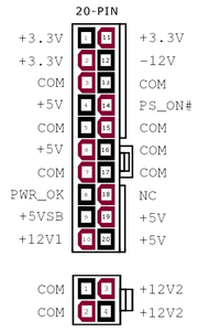
Originally, the motherboard was powered by one 20-pin connector. An ATX power supply provides a number of peripheral power connectors and (in modern systems) two connectors for the motherboard: an 8-pin (or 4+4-pin) auxiliary connector providing additional power to the CPU and a main 24-pin power supply connector, an extension of the original 20-pin version. 20-pin MOLEX 39-29-9202 at the motherboard. 20-pin MOLEX 39-01-2200 at the cable. The connector pin pitch is 4.2 mm (one sixth of an inch).

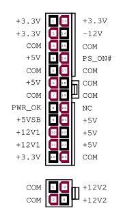
Pinouts of ATX 2.x motherboard power connectors, 24-pin (top) and four-pin "P4" (bottom), as viewed into mating side of the plugs

ATX 20-PIN


24-pin ATX motherboard power plug; pins 11, 12, 23 and 24 form a detachable separate four-pin plug, making it backward-compatible with 20-pin ATX receptacles
| Color | Signal[upper-alpha 1] | Pin[upper-alpha 2] | Pin[upper-alpha 2][upper-alpha 3] | Signal[upper-alpha 1] | Color |
|---|---|---|---|---|---|
| Orange | +3.3 V | 1 | 13 | +3.3 V | Orange |
| +3.3 V sense[upper-alpha 4] | Brown | ||||
| Orange | +3.3 V | 2 | 14 | −12 V | Blue |
| Black | Ground | 3 | 15 | Ground | Black |
| Red | +5 V | 4 | 16 | Power on[upper-alpha 5] | Green |
| Black | Ground | 5 | 17 | Ground | Black |
| Red | +5 V | 6 | 18 | Ground | Black |
| Black | Ground | 7 | 19 | Ground | Black |
| Grey | Power good[upper-alpha 6] | 8 | 20 | Reserved[upper-alpha 7] | None |
| Purple | +5 V standby | 9 | 21 | +5 V | Red |
| Yellow | +12 V | 10 | 22 | +5 V | Red |
| Yellow | +12 V | 11 | 23 | +5 V | Red |
| Orange | +3.3 V | 12 | 24 | Ground | Black |
| |||||
| Color | Signal | Pin | Pin | Signal | Color |
|---|---|---|---|---|---|
| Green | PS_ON# | 1 | 6 | PWR_OK | Gray |
| Black | COM | 2 | 7 | +12 VSB | Purple |
| Black | COM | 3 | 8 | +12 V1 DC | Yellow |
| Black | COM | 4 | 9 | +12 V1 DC | Yellow |
| TBD | Reserved | 5 | 10 | +12 V1 DC Voltage Sensing Pin |
Yellow |
| Pins | Female/receptacle on PS cable |
Male/vertical header on PCB |
Male/plug extender cable |
|---|---|---|---|
| 4-pin | 39-01-2040 | 39-28-1043 | 39-01-2046 |
| 20-pin | 39-01-2200 | 39-28-1203 | 39-01-2206 |
| 24-pin | 39-01-2240 | 39-28-1243 | 39-01-2246 |
Four wires have special functions:
- PS_ON# (power on) is a signal from the motherboard to the power supply. When the line is connected to ground (by the motherboard), the power supply turns on. It is internally pulled up to +5 V inside the power supply.
- PWR_OK ("power good") is an output from the power supply that indicates that its output has stabilized and is ready for use. It remains low for a brief time (100–500 ms) after the PS_ON# signal is pulled low.
- +5 VSB (+5 V standby) supplies power even when the rest of the supply wire lines are off. This can be used to power the circuitry that controls the power-on signal.
- +3.3 V sense should be connected to the +3.3 V on the motherboard or its power connector. This connection allows remote sensing of the voltage drop in the power-supply wiring. Some manufacturers also provided a +5 V sense wire (typically colored pink) connected to one of the red +5 V wires on some models of power supply; however, the inclusion of such wire was a non-standard practice and was never part of any official ATX standard.
Generally, supply voltages must be within ±5% of their nominal values at all times. The little-used negative supply voltages, however, have a ±10% tolerance. There is a specification for ripple in a 10 Hz–20 MHz bandwidth:
| Supply (V) | Tolerance | Range, min. to max. (V) | Ripple, p. to p., max. (mV) |
|---|---|---|---|
| +5 | ±5% (±0.25 V) | +4.75 V to +5.25 | 50 |
| −5 | ±10% (±0.50 V) | −4.50 V to −5.50 | 50 |
| +12 | ±5% (±0.60 V) | +11.40 V to +12.60 | 120 |
| −12 | ±10% (±1.20 V) | −10.80 V to −13.20 | 120 |
| +3.3 | ±5% (±0.165 V) | +3.135 V to +3.465 | 50 |
| +5 standby | ±5% (±0.25 V) | +4.75 V to +5.25 | 50 |
The 20–24-pin Molex Mini-Fit Jr. has a power rating of 600 volts, 8 amperes maximum per pin (while using 18 AWG wire). As large server motherboards and 3D graphics cards have required progressively more and more power to operate, it has been necessary to revise and extend the standard beyond the original 20-pin connector, to allow more current using multiple additional pins in parallel. The low circuit voltage is the restriction on power flow through each connector pin; at the maximum rated voltage, a single Mini-Fit Jr pin would be capable of 4800 watts.
Physical characteristics[]
ATX power supplies generally have the dimensions of 150 × 86 × 140 mm (5.9 × 3.4 × 5.5 in), with the width and height being the same as the preceding LPX (Low Profile eXtension) form factor (which are often incorrectly referred to as "AT" power supplies due to their ubiquitous use in later AT and Baby AT systems, even though the actual AT and Baby AT power supply form factors were physically larger) and share a common mounting layout of four screws arranged on the back side of the unit. That last dimension, the 140 mm depth, is frequently varied, with depths of 160, 180, 200 and 230 mm used to accommodate higher power, larger fan and/or modular connectors.
Main changes from AT and LPX designs[]
Power switch[]
Original AT cases (flat case style) have an integrated power switch that protruded from the power supply and sits flush with a hole in the AT chassis. It utilizes a paddle-style DPST switch and is similar to the PC and PC-XT style power supplies.
Later AT (so-called "Baby AT") and LPX style computer cases have a power button that is directly connected to the system computer power supply (PSU). The general configuration is a double-pole latching mains voltage switch with the four pins connected to wires from a four-core cable. The wires are either soldered to the power button (making it difficult to replace the power supply if it failed) or blade receptacles were used.


Typical ATX 1.3 power supply. From left to right, the connectors are 20-pin motherboard, 4-pin "P4 connector", fan RPM monitor (note the lack of a power wire), SATA power connector (black), "Molex connector" and floppy connector.

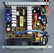
Interior view in an ATX power supply
An ATX power supply is typically controlled by an electronic switch connected to the power button on the computer case and allows the computer to be turned off by the operating system. In addition, many ATX power supplies have an equivalent-function manual switch on the back that also ensures no power is being sent to the components. When the switch on the power supply is turned off, however, the computer cannot be turned on with the front power button.
Power connection to the motherboard[]
The power supply's connection to the motherboard was changed from the older AT and LPX standards; AT and LPX had two similar connectors that could be accidentally interchanged by forcing the different keyed connectors into place, usually causing short-circuits and irreversible damage to the motherboard (the rule of thumb for safe operation was to connect the side-by-side connectors with the black wires together). ATX uses one large, keyed connector which can not be connected incorrectly. The new connector also provides a 3.3 volt source, removing the need for motherboards to derive this voltage from the 5 V rail. Some motherboards, particularly those manufactured after the introduction of ATX but while LPX equipment was still in use, support both LPX and ATX PSUs.
If using an ATX PSU for purposes other than powering an ATX motherboard, power can be fully turned on (it is always partly on to operate "wake-up" devices) by shorting the "power-on" pin on the ATX connector (pin 16, green wire) to a black wire (ground), which is what the power button on an ATX system does. A minimum load on one or more voltages may be required (varies by model and vendor); the standard does not specify operation without a minimum load and a conforming PSU may shut down, output incorrect voltages, or otherwise malfunction, but will not be hazardous or damaged. An ATX power supply is not a replacement for a current-limited bench laboratory DC power supply, instead it is better described as a bulk DC power supply.
Airflow[]
The original ATX specification called for a power supply to be located near to the CPU with the power supply fan drawing in cooling air from outside the chassis and directing it onto the processor. It was thought that in this configuration, cooling of the processor would be achievable without the need of an active heatsink.[1] This recommendation was removed from later specifications; modern ATX power supplies usually exhaust air from the case.
ATX power supply revisions[]
Original ATX[]
ATX, introduced in late 1995, defined three types of power connectors:
- 4-pin "Molex connector" — transferred directly from AT standard: +5 V and +12 V for P-ATA hard disks, CD-ROMs, 5.25 inch floppy drives and other peripherals.
- 4-pin Berg floppy connector — transferred directly from AT standard: +5 V and +12 V for 3.5 inch floppy drives and other peripherals.
- 20-pin Molex Mini-fit Jr. ATX motherboard connector — new to the ATX standard.
- A supplemental 6-pin AUX connector providing additional 3.3 V and 5 V supplies to the motherboard, if needed. This was used to power the CPU in motherboards with CPU voltage regulator modules which required 3.3 volt and/or 5 volt rails and could not get enough power through the regular 20-pin header.
The power distribution specification defined that most of the PSU's power should be provided on 5 V and 3.3 V rails, because most of the electronic components (CPU, RAM, chipset, PCI, AGP and ISA cards) used 5 V or 3.3 V for power supply. The 12 V rail was only used by computer fans and motors of peripheral devices (HDD, FDD, CD-ROM, etc.)
ATX12V 1.x[]
While designing the Pentium 4 platform in 1999/2000, the standard 20-pin ATX power connector was found insufficient to meet increasing power-line requirements; the standard was significantly revised into ATX12V 1.0 (ATX12V 1.x is sometimes inaccurately called ATX-P4). ATX12V 1.x was also adopted by AMD Athlon XP and Athlon 64 systems. However, some early model Athlon XP and MP boards (including some server boards) and later model lower-end motherboards do not have the 4-pin connector as described below.
Numbering of the ATX revisions may be a little confusing: ATX refers to the design, and goes up to version 2.2 in 2004 (with the 24 pins of ATX12V 2.0) while ATX12V describes only the PSU. For instance, ATX 2.03 is pretty commonly seen on PSU from 2000 & 2001 and often include the P4 12V connector, even if the norm itself does not define it yet!
- ATX12V 1.0
The main changes and additions in ATX12V 1.0 (released in February 2000) were:
- Increased the power on the 12 V rail (power on 5 V and 3.3 V rails remained mostly the same).
- An extra 4-pin mini fit JR (Molex 39-01-2040), 12-volt connector to power the CPU.
Formally called the +12 V Power Connector, this is commonly referred to as the P4 connector because this was first needed to support the Pentium 4 processor.
Before the Pentium 4, processors were generally powered from the 5 V rail. Later processors operate at much lower voltages, typically around 1 V and some draw over 100 A. It is infeasible to provide power at such low voltages and high currents from a standard system power supply, so the Pentium 4 established the practice of generating it with a DC-to-DC converter on the motherboard next to the processor, powered by the 4-pin 12 V connector.
- ATX12V 1.1
This is a minor revision from August 2000. The power on the 3.3 V rail was slightly increased and other smaller changes were made.
- ATX12V 1.2
A relatively minor revision from January 2002. The only significant change was that the −5 V rail was no longer required (it became optional). This voltage was required by the ISA bus, which is no longer present on almost all modern computers.
- ATX12V 1.3
Introduced in April 2003 (a month after 2.0). This standard introduced some changes, mostly minor. Some of them are:
- Slightly increased the power on 12 V rail.
- Defined minimal required PSU efficiencies for light and normal load.
- Defined acoustic levels.
- Introduction of Serial ATA power connector (but defined as optional).
- Guidance for the −5 V rail was removed (but it was not prohibited).
ATX12V 2.x[]
ATX12V 2.x brought a very significant design change regarding power distribution. By analyzing the power demands of then-current PCs, it was determined that it would be much cheaper and more practical to power most PC components from 12 V rails, instead of from 3.3 V and 5 V rails.
In particular, PCI Express expansion cards take much of their power from the 12 V rail (up to 5.5 A), while the older AGP graphics cards took only up to 1 A on 12 V and up to 6 A on 3.3 V. The CPU is also driven by a 12 V rail, while it was done by a 5 V rail on older PCs (before the Pentium 4).
- ATX12V 2.0


ATX-450PNF by FSP Group
The power demands of PCI Express were incorporated in ATX12V 2.0 (introduced in February 2003), which defined quite different power distribution from ATX12V 1.x:
- Most power is now provided on 12 V rails. The standard specifies that two independent 12 V rails (12 V2 for the four-pin connector and 12 V1 for everything else) with independent overcurrent protection are needed to meet the power requirements safely (some very high power PSUs have more than two rails; recommendations for such large PSUs are not given by the standard).
- The power on 3.3 V and 5 V rails was significantly reduced.
- The ATX motherboard connector was extended to 24 pins. The extra four pins provide one additional 3.3 V, 5 V and 12 V circuit.
- The six-pin AUX connector from ATX12V 1.x was removed because the extra 3.3 V and 5 V circuits which it provided are now incorporated in the 24-pin ATX motherboard connector.
- The power supply is required to include a Serial ATA power cable.
- Many other specification changes and additions
- ATX12V v2.01
This is a minor revision from June 2004. An errant reference for the −5 V rail was removed. Other minor changes were introduced.
- ATX12V v2.1
This is a minor revision from March 2005. The power was slightly increased on all rails. Efficiency requirements changed.
- ATX12V v2.2
Also released in March 2005 it includes corrections and specifies High Current Series wire terminals for 24-pin ATX motherboard and 4-pin +12 V power connectors.
- ATX12V v2.3
Effective March 2007. Recommended efficiency was increased to 80% (with at least 70% required) and the 12 V minimum load requirement was lowered. Higher efficiency generally results in less power consumption (and less waste heat) and the 80% recommendation brings supplies in line with new Energy Star 4.0 mandates. The reduced load requirement allows compatibility with processors that draw very little power during startup. The absolute over-current limit of 240 VA per rail was removed, allowing 12 V lines to provide more than 20 A per rail.
- ATX12V v2.31
This revision became effective in February 2008. It added a maximum allowed ripple/noise specification of 400 millivolts to the PWR_ON and PWR_OK signals, requires that the DC power must hold for more than 1 millisecond after the PWR_OK signal drops, clarified country-specific input line harmonic content and electromagnetic compatibility requirements, added a section about Climate Savers, updated recommended power supply configuration charts, and updated the cross-regulation graphs.
- ATX12V v2.32
This the unofficial name given to the later revisions of the v2.31 spec.
- ATX12V v2.4
The ATX12V specifications were published in April 2013. It is specified in Revision 1.31 of the 'Design Guide for Desktop Platform Form Factors', which names this as ATX12V version 2.4.
- ATX12V v2.52
The specifications for ATXV12 2.52 were released in June 2018 and introduced support for Alternative Sleep Mode (ASM) which supersedes the traditional S3 power state. Windows 10 implements this functionality as Modern Standby.
ATX power supply derivatives[]
ATX12VO[]
Standing for ATX 12-volt-only, this is a new specification published by Intel in 2019, aimed at pre-built systems in the first run, and possibly affecting DIY and "high expandability" systems (defined as a pre-built computer with a discrete GPU) when a market emerges. It was motivated by stricter power efficiency requirements by the California Energy Commission going into effect in 2021. Several OEMs were already using a similar design with proprietary connectors and this effectively standardizes those.
Under this standard, power supplies provide only a 12V output. ATX12VO introduces a new 10-pin connector to supply the motherboard, replacing the 24-pin ATX12V connector. This greatly simplifies power supplies, but moves DC-to-DC conversion and some connectors to the motherboard instead. Notably, SATA power connectors, which include 3.3V and 5V pins, need to move to the motherboard instead of being connected directly to the power supply.
SFX[]


An SFX power supply unit
SFX is merely a design for a small form factor (SFF) power supply casing, with the power specifications almost identical to ATX. Thus, an SFX power supply is mostly pin-compatible with the ATX power supply as the main difference is its reduced dimensions; the only electrical difference is that the SFX specifications do not require the −5 V rail. Since −5 V is required only by some ISA-bus expansion cards, this is not an issue with modern hardware and decreases productions costs. As a result, ATX pin 20, which carried −5 V, is absent in current power supplies; it was optional in ATX and ATX12V version 1.2 and deleted as of ATX version 1.3.
SFX has dimensions of 125 × 63.5 × 100 mm (width × height × depth), with a 60 mm fan, compared with the standard ATX dimensions of 150 × 86 × 140 mm. Optional 80 or 40 mm fan replacement increases or decreases the height of an SFX unit.
Some manufacturers and retailers incorrectly market SFX power supplies as µATX or MicroATX power supplies.
Some manufacturers make SFX-L dimensions of 125 × 63.5 × 130 mm to accommodate a 120 mm fan.
TFX[]


A TFX power supply unit
Thin Form Factor is another small power supply design with standard ATX specification connectors. Generally dimensioned (W × H × D): 85 × 64 × 175 mm (3.34 × 2.52 × 6.89 in).
WTX[]
Provides a WTX style motherboard connector which is incompatible with the standard ATX motherboard connector.
AMD GES[]
This is an ATX12V power supply derivative made by AMD to power its Athlon MP (dual processor) platform. It was used only on high-end Athlon MP motherboards. It has a special 8-pin supplemental connector for motherboard, so an AMD GES PSU is required for such motherboards (those motherboards will not work with ATX(12 V) PSUs).
a. ATX12V-GES 24-pin P1 motherboard connector. The pinout on the motherboard connector is as follows when viewing the motherboard from above:
| Pin | Signal | Colour | Pin | Signal | Colour |
|---|---|---|---|---|---|
| 12 | 12 V | Yellow | 24 | 12 V | Yellow |
| 11 | 12 V | Yellow | 23 | GND | Black |
| 10 | GND | Black | 22 | GND | Black |
| 9 | GND | Black | 21 | 3.3 V | Orange |
| 8 | 3.3 V | Orange | 20 | 3.3 V | Orange |
| 7 | 3.3 V | Orange | 19 | 3.3 V | Orange |
| 6 | GND | Black | 18 | GND | Black |
| 5 | PS_ON_N | Green | 17 | −12 V | Blue |
| 4 | GND | Black | 16 | 5 V SB | Purple |
| 3 | GND | Black | 15 | GND | Black |
| 2 | 5 V | Red | 14 | 5 V | Red |
| 1 | 5 V | Red | 13 | 5 V | Red |
b. ATX12V-GES 8-pin P2 motherboard connector. This pinout on the motherboard connector is as follows when viewing the motherboard from above:
| Pin | Signal | Colour | Pin | Signal | Colour |
|---|---|---|---|---|---|
| 4 | GND | Black | 8 | 12 V | Yellow striped black |
| 3 | GND | Black | 7 | 12 V | Yellow striped black |
| 2 | PWR_OK | Gray | 6 | 12 V | Yellow striped black |
| 1 | 5 V | Red | 5 | GND | Black |
EPS12V[]
EPS12V is defined in Server System Infrastructure (SSI) and used primarily by SMP/multi-core systems such as Core 2, Core i7, Opteron and Xeon. It has a 24-pin ATX motherboard connector (same as ATX12V v2.x), an 8-pin secondary connector and an optional 4-pin tertiary connector. Rather than include the extra cable, many power supply makers implement the 8-pin connector as two combinable 4-pin connectors to ensure backwards compatibility with ATX12V motherboards.
Recent specification changes and additions[]
High-performance video card power demands dramatically increased during the 2000s and some high-end graphics cards have power demands that exceed AGP or PCIe slot capabilities. For these cards, supplementary power was delivered through a standard 4-pin peripheral or floppy power connector. Midrange and high-end PCIe graphics cards manufactured after 2004 typically use a standard 6 or 8-pin PCIe power connector directly from the PSU.
Interchanging PSUs[]
Although the ATX power supply specifications are mostly vertically compatible in both ways (both electrically and physically), there are potential issues with mixing old motherboards/systems with new PSUs and vice versa. The main issues to consider are the following:
- The power allocation between 3.3 V, 5 V and 12 V rails is very different between older and newer ATX PSU designs, as well as between older and newer PC system designs.
- Older PSUs may not have connectors which are required for newer PC systems to properly operate.
- Newer systems generally have higher power requirements than older systems.
This is a practical guidance what to mix and what not to mix:
- Older systems (before Pentium 4 and Athlon XP platforms) were designed to draw most power from 5 V and 3.3 V rails.
- Because of the DC-DC converters on the motherboard that convert 12 V to the low voltages required by the Intel Pentium 4 and AMD Athlon XP (and subsequent) processors, such systems draw most of their power from the 12 V rail.
- Original ATX PSUs have power distribution designed for pre-P4/XP PCs. They lack the supplemental 4-pin 12-volt CPU power connector, so they most likely cannot be used with P4/XP or newer motherboards. Adapters do exist but power drain on the 12 V rail must be checked very carefully. There is a chance it can work without connecting the 4-pin 12 V connector, but caution is advised.
- ATX12V 1.x PSUs have power distribution designed for P4/XP PCs, but they are also greatly suitable for older PCs, since they give plenty of power (relative to old PCs' needs) both on 12 V and on 5 V/3.3 V. It is not recommended to use ATX12V 1.x PSUs on ATX12V 2.x motherboards because those systems require much more power on 12 V than ATX12V 1.x PSUs provide.
- ATX12V 2.x PSUs have power distribution designed for late P4/XP PCs and for Athlon 64 and Core Duo PCs. They can be used with earlier P4/XP PCs, but the power distribution will be significantly suboptimal, so a more powerful ATX12V 2.0 PSU should be used to compensate for that discrepancy. ATX12V 2.x PSUs can also be used with pre-P4/XP systems, but the power distribution will be greatly suboptimal (12 V rails will be mostly unused, while the 3.3 V/5 V rails will be overloaded), so this is not recommended.
- Systems that use an ISA bus should have a PSU that provides the −5 V rail, which became optional in ATX12V 1.2 and was subsequently phased out by manufacturers.
Some proprietary brand-name systems require a matching proprietary power supply, but some of them may also support standard and interchangeable power supplies.
Efficiency[]
- See also: Green computing, 80 Plus
Efficiency in power supplies means the extent to which power is not wasted in converting electricity from a household supply to regulated DC. Computer power supplies vary from around 70% to over 90% efficiency.
Various initiatives exist to improve the efficiency of computer power supplies. Climate Savers Computing Initiative promotes energy saving and reduction of greenhouse gas emissions by encouraging development and use of more efficient power supplies. 80 PLUS certifies a variety of efficiency levels for power supplies and encourages their use via financial incentives. Efficient power supplies also save money by wasting less power; as a result they use less electricity to power the same computer, and they emit less waste heat which results in significant energy savings on central air conditioning in the summer. The gains of using an efficient power supply are more substantial in computers that use a lot of power.
Although a power supply with a larger than needed power rating will have an extra margin of safety against overloading, such a unit is often less efficient and wastes more electricity at lower loads than a more appropriately sized unit. For example, a 900-watt power supply with the 80 Plus Silver efficiency rating (which means that such a power supply is designed to be at least 85-percent efficient for loads above 180 W) may only be 73% efficient when the load is lower than 100 W, which is a typical idle power for a desktop computer. Thus, for a 100 W load, losses for this supply would be 37 W; if the same power supply was put under a 450 W load, for which the supply's efficiency peaks at 89%, the loss would be only 56 W despite supplying 4.5 times the useful power. For a comparison, a 500-watt power supply carrying the 80 Plus Bronze efficiency rating (which means that such a power supply is designed to be at least 82-percent efficient for loads above 100 W) may provide an 84-percent efficiency for a 100 W load, wasting only 19 W.
Notes[]
- ↑ For boards which take expansion slots, the length of the expansion card aligns with the depth of the system board. The case may support cards longer than the depth of the mainboard.
References[]

|
This page uses content that though originally imported from the Wikipedia article ATX might have been very heavily modified, perhaps even to the point of disagreeing completely with the original wikipedia article. The list of authors can be seen in the page history. The text of Wikipedia is available under the Creative Commons Licence. |